
Categories
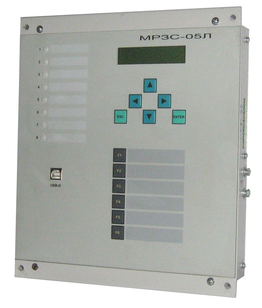
MРЗС-05Л AИAР.466452.001-12.2

Used as the main protection with the function of ACB on the busbar coupler.
It performs the following functions:
Provides control and measurement of the following values:
- phase currents 1a, 1c, 1b - from 0,1 to 30 Iн (Iн = 5 А);
- currents of positive and reverse sequences;
- three-phase / line voltages of the first busbar section;
- three-phase / line voltages of the second busbar section;
- angles between all currents and voltages;
- network frequencies in both sections;
- active power with a sign;
- reactive power with a sign;
- full power;
- power factor;
- active energy in the forward and reverse directions;
- reactive energy in four quadrants.
Relay protection functions:
- four-stage overcurrent protection (OCP), has the following stages:
- 1 - stage with definite time delay (current pinch-off), or with the possibility of a voltage triggering, or directional OCP with an independent time delay;
- 2 - stage with an indefinite time delay with the possibility of voltage triggering or with a definite time delay (in accordance with IЕС 255-4 types A, B, C, characteristics RТ-80, RТV-1), or directional OCP with indefinite time delay;
- 3 - stage with a definite time delay (overload protection) with the possibility of voltage triggering or directional OCP;
- 4 - stage with a definite time delay (overload protection) with the possibility of voltage triggering or directional OCP.
- two-stage undervoltage protection with the ability to control the current and the inclusion of triggers for AND or OR.
- two-stage overvoltage protection with the inclusion of triggers for AND or OR.
- negative phase-sequence protection (NPSP), reacts to the ratio of the negative sequence current to the direct sequence current (phase failure monitoring (PFM));
- arc fault protection (AFP): start of AFP is carried out through a discrete input from an external arc protection sensor with the ability of current control;
- circuit-breaker failure protection (CBFP) with current control: CBFP is initiated when cut-off tripping events or via a binary input. CBFP has two stages in response time.
- implementation of busbar protection scheme (BPS).
- synchronism control.
Automation functions:
- Transfer switch (TS) with the ability to work not only to reduce, but also to increase the voltage;
- four-time recloser (AR). The AR is started from OCP. Provides the ability to block reclosing through a discrete input;
- circuit breaker control. The circuit breaker can be switched on and off both from the device and via a discrete input (pulsed). If there is a command to cut off the circuit breaker, the on signal is blocked;
- acceleration of OCP after the switch is turned on, or if the second stage of the OCP is forced into the accelerated mode.
- Circuit breaker closing and opening monitoring;
- control of commutation life of switch.
Defined functions, triggers and logical elements:
- number of defined functions - 8;
- number of defined triggers - 4, the status of triggers is stored in non-volatile memory;
- logical elements AND, OR, NOT, EXCLUSIVE-OR.
Emergency registrar of oscillograms of currents with recording of discrete signals:
- parameterizable duration of pre-emergency and emergency recording.
- resolution of the recorder by analog signals - not more than 1.25 ms.
- total recording time - 66 s.
Discrete event recorder:
- 48 recent events,
- up to 43 entries in each accident with a discreteness in time - 1 ms,
- for each accident the following are recorded:
- all input and output discrete signals, with the fixation of arrival and departure time;
- maximum value of phase current with fixation of remaining currents and voltages;
- maximum value of the ratio of the current of the negative sequence to the current of the direct
- maximum value of phase or linear voltages with fixation of remaining currents and voltages;
- minimum value of phase or linear voltages with fixation of remaining currents and voltages.
Determining the fault location.
Energy metering:
- active energy - in two directions;
- reactive energy - in four quadrants.
Four groups of settings for all protections.
Short-circuit current auxiliary power supply. If the power supply of the device at the power input of 220 V (or 110 V) The device can be powered from current transformers of phases A and C. In this case, the magnitude of the current must be 4 A or more for one of the phases or for the total of two phases.
Binary inputs feeding from internal source - from the DIP output, two discrete inputs can be energized
Number of freely programmable inputs, outputs, indicators:
- discrete inputs - 10, with the possibility of autonomous power supply of a discrete input;
- discrete relay outputs - 10, without and with the memorization, realization of ShMS;
- LED indicators - 8, with and without memory.
- All inputs, outputs, indicators are freely programmable.
Connection diagram MRZS-05L AIAR.466452.001-12.2, (-32.2)
 str.1")
 str.2")
Overall and mounting dimensions MRZS-05L AIAR.466452.001 (-12), (-12.1) and (-12.2)
,(12.1),(12.2)")
,(12.1),(12.2)")
,(12.1),(12.2)")
,(12.1),(12.2)")
,(12.1),(12.2)")
,(12.1),(12.2)")
Software Wisinet2 for МРЗС-05Л, МРЗС-05Д, MRZS
Please pay attention! Many new versions of devices have been added for corrective work, the program must save the /data folder (with your archives), delete the WisiNet2 installation program, download the archive from the website and install the Wisinet2 program and replace the new /data folder with your previous oneDownload Wisinet 2