
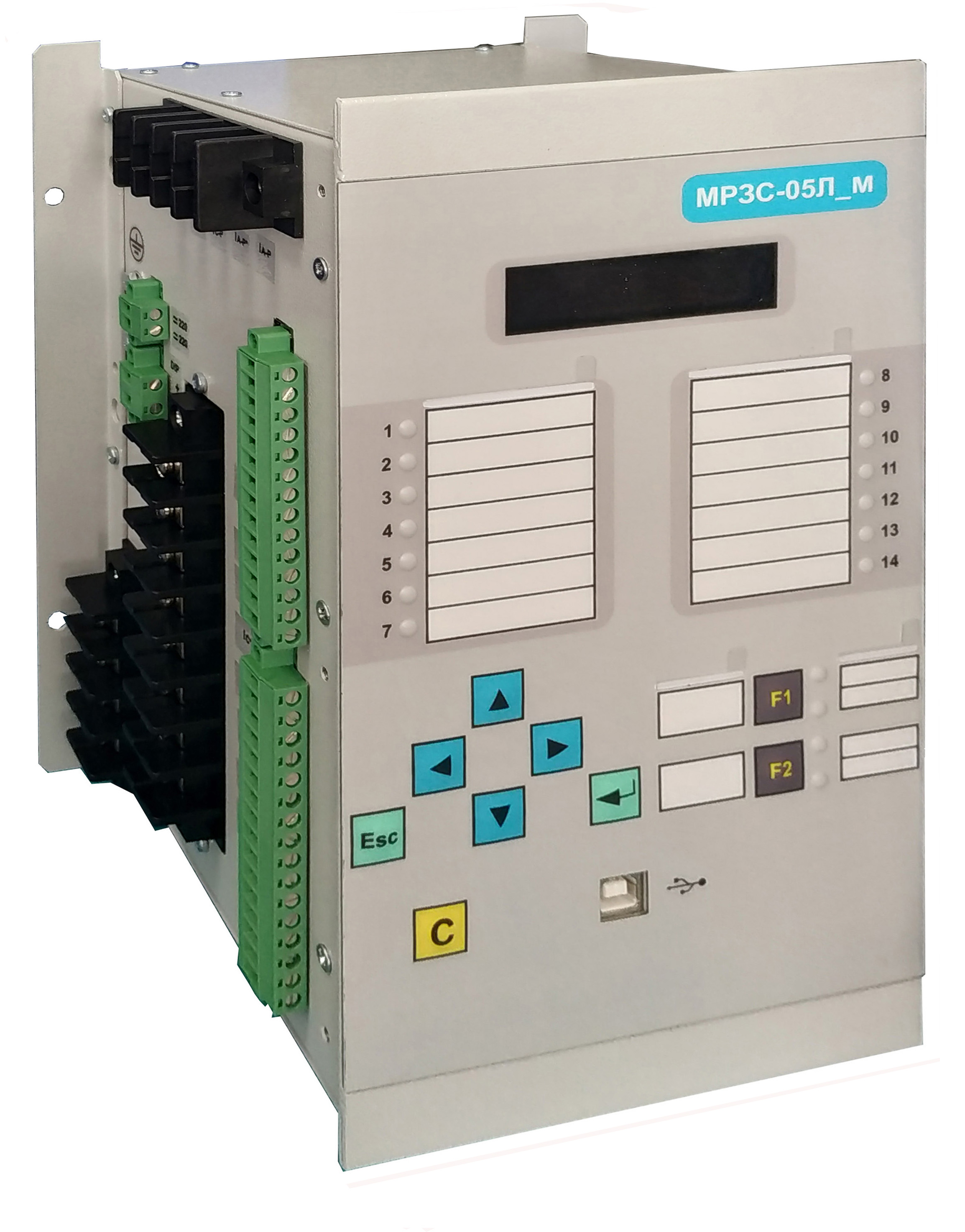
MРЗС-05Л_м AИAР.466452.001-40.1 (with shunting)

Used as protection of the feeder cable and overhead lines in networks with compensated and uncompensated capacitive currents. Directional ground-fault protection allows the device to be installed on connections that have a capacitive current of 40% or more of the capacitive current of the substation. It has a large number of service functions. Devices can be placed: in the relay compartments of single-end service assembled chambers, switchgears and control gears, outdoor switchgears (YAKNO), panels, in control cabinets.
Performs the following functions:
Provides control and measurement of the following values:
- phase currents 1a, 1c, 1b (calculated) - from 0,1 to 30 Iн;
- zero sequence current - from 0.01 to 2 A;
- residual voltage 3Uo or Uab to - 150 B
- direct sequence current;
- negative sequence current.
Relay protection functions:
- four-stage overcurrent protection (OCP), has the following stages:
- 1 stage with definite time delay (current cut off);
- 2 stage with definite time delay or with a current definite time delay (in accordance with IES 255-4 types A, B, C, characteristics RТ-80, RТV-1);
- 3 stage with definite time delay or with a current definite time delay (in accordance with IES 255-4 types A, B, C, characteristics RТ-80, RТV-1);
- 4 stage with definite time delay (overload protection).
- blocking of the overcurrent protection from magnetizing-current inrush.
- two-stage directional ground fault protection GFP is triggered by a forward or reverse power direction.
- non-directional ground-fault protection according to 3Io can be of two versions:
- 1) protection reacts to the residual current of the industrial frequency 3Io (analogue of the relay PTZ-51);
- 2) protection by the sum of the residual harmonic currents.
- zero-phase-sequence voltage protection 3Uо (RNN).
- negative phase-sequence protection (NPSP), reacts to the ratio of the negative sequence current to the direct sequence current (phase failure monitoring (PFM)).
- external protection with the control of any current or voltage from the supplied to the device is triggered by a signal from a discrete input.
- circuit-breaker failure protection (CBFP) with current control: the breaker failure protection is initiated when the protection is tripped or disconnected. The breaker failure protection has two stages by response time.
- implementation of busbar protection scheme (BPS).
Automation functions:
- two-time recloser (AR). The AR is started from OCP. Provides the ability to block reclosing through a discrete input.
- circuit breaker control. The circuit breaker can be switched on and off both from the device and via a discrete input (pulsed). If there is a command to turn off the circuit breaker, the switch-on signal is blocked.
- acceleration of the overcurrent protection by the fact of switching on the circuit breaker or the forced setting of the second and third stages of the overcurrent protection to the accelerated mode.
- circuit breaker closing and opening circuits monitoring.
- control of the integrity of the switch-on coil.
- tripping coil of circuit breaker integrity control.
- control of the switching resource of the circuit breaker.
Defined functions, triggers and logical elements:
- number of defined functions - 8;
- number of detected triggers is 4, the state of the triggers is stored in non-volatile memory;
- logical elements AND, OR, NOT, EXCLUSIVE-OR.
Emergency registrar of oscillograms of currents with recording of discrete signals:
- parameterizable duration of pre-emergency and emergency recording.
- resolution of the recorder by analog signals - no more than 1.25 ms.
- total recording time - 90 s.
Discrete event recorder:
- 60 recent events,
- up to 54 records in each accident with a discreteness in time - 1 ms.
- discrete inputs - 6, with the possibility of autonomous power supply of a discrete input;
- discrete relay outputs - 7 (one of the outputs is a bistable relay), without and with memorization, implementation of the ShMS;
- LED indicators - 14, with and without memory.
- Two freely programmable buttons with the ability to switch to the "key" mode. Can be used to turn on / off the circuit breaker or as I / O keys for protection and automation functions. They have LED position light.
- Separate reset button for indication and signal relays.
- Multilingual menu - 3 languages supported.
- Provides input-output from the work of all protections or their individual stages.
- Working with an external computer via the USB port.
- To operate the device in a local network, an RS-485 interface is provided.
- Communication protocol - ModBus RTU.
- Support UnixTime.
- Universal brackets for mounting the device in a cabinet or on a panel.
- Update software via USB.
Bypassing/disposing of current circuits
Short-circuit current auxiliary power supply. If the power supply of the device at the power input of 220 V (or 110 V)
The device can be powered from current transformers of phases A and C. In this case, the magnitude of the current must be 4 A or more for one of the phases or for the total of two phases.</Binary inputs feeding from internal source - From the DIP output, two discrete inputs can be energized
Number of freely programmable inputs, outputs, indicators:
Binary inputs feeding from internal source - From the DIP output, two discrete inputs can be energized
Number of freely programmable inputs, outputs, indicators:
Software WisiNet_2 for МРЗС-05Л, МРЗС-05Д, MRZS
Please pay attention! Many new versions of devices have been added for corrective work, the program must save the /data folder (with your archives), delete the WisiNet2 installation program, download the archive from the website and install the Wisinet2 program and replace the new /data folder with your previous oneDownload Wisinet 2
If you have a version of the WisiNet_2 program higher than v.22.1, you can simply update the jar fileUpdate programm Wisinet 2 download