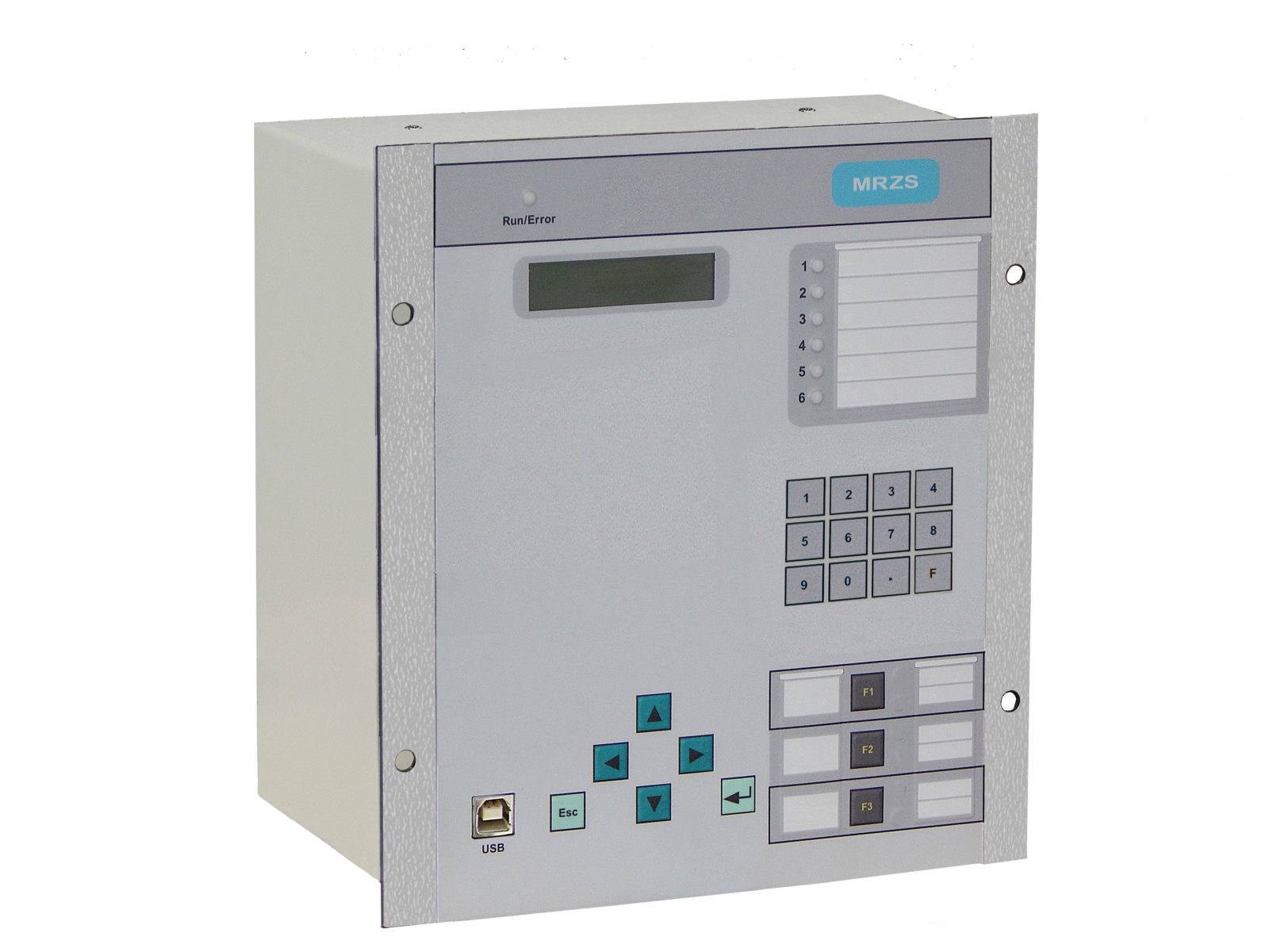
MRZS-R
It is used at power facilities to realize automatic regulation of the on-load tap changing of power transformers with both smoothly and with a sharply varying load. Used to complete both new power transformers, and to replace automation devices of on-load tap changing of old types. The device fulfills all the functions of the earlier automatic devices of automatic on-load tap changing of type ART-1N (BAR), ART-1M, as well as a number of other additional functions. The scheme of the external connections of the device is maximally adapted to the typical for on-load tap changing control circuits of CIS countriies.
Performs the following functions
Control and measurement
- line voltage of the main channel from TV1;
- line voltage of auxiliary channel from TV2 installed on another section of the bus, powered by this transformer;
- current from the current transformers of one of the phases of connection, the load of which provides current compensation - main channel;
- current from the current transformers of one of the phases of another connection, by the load of which current compensation can be made - auxiliary channel.
Automation functions:
- automatic regulation of the voltage of the power transformer under load for monitoring the voltage level from the main input (ТV1);
- control by additional input (ТV2) voltage on another section of the bus, powered by this transformer and limiting the regulation when the voltage goes beyond the limits set by the setpoint. Switching the inputs of controlled voltage sources (TV1 or TV2) as a reference on discrete input or operationally;
- counterload voltage control by current of one of connections;
- interlocking of the automatic control of the on-load tap-changer during overloading of the transformer by load current.
Relay protection functions:
- protection from emergency modes, caused by improper operation of on-load tap changing;
- under-voltage protection PVmin;
- maximum voltage protection PVmax.
Monitoring, registration and alarm functions:
- monitoring and indication of on-load tap changing position;
- monitoring of the operation of on-load tap changing drive in all modes of its operation;
- control of on-load tap changing drive:
-
- remote, through discrete inputs;
- manual, using the buttons on the front panel of the device;
- telecontrol via communication channels;
- automatic;
- accounting of on-load tap changing drive resource;
- emergency recorder of actual values of analog signals:
- parameterizable duration of pre-emergency recording from 80 ms to 26 s;
- resolution of the recorder - from 80 to 800 ms;
- total duration of the recording - 30 000 samples,
- discrete signal recorder:
- 64 recent events;
- up to 80 records in each accident with a fixed value:
- maximum current of the main channel;
- maximum voltages of the main and auxiliary channels;
- minimum voltage of the main channel at the moment of PVmin set-up.
-
Enhanced logic functions:
- number of defined functions - 8;
- number of defined triggers - 4;
- status of triggers is stored in non-volatile memory;
Enhanced logic allows to complement existing functions, and create new ones.
Service functions:
- freely assignable inputs;
- freely assignable outputs;
- freely assignable LEDs;
- two groups of settings for all protections;
- multilingual menu - 3 languages supported;
- three freely programmable buttons;
- work with an external computer is carried out through the USB port.
Interfaces and communication protocols:
- Interface RS 485 - Communication protocol Modbus RTU;
- Interface USB;
| Hardware configuration parameters | B |
|---|---|
| Current sensors | 2I |
| Voltage sensors | 2U |
| Connection of selsyn sensors | + |
| Connection of resistive sensors | + |
| Number of discrete inputs | 8 |
| Number of discrete outputs: with NO contact element with change-over contact power | 9 (7) 4 4 1 |
| Number of LEDs, of them programmable | 7 6 |
| Function keys, of them with key mode | 3 - |
| Communication interfaces RS485 USB | 1 1 |
Overall and mounting dimensions MRZS-R
Overall and connecting dimensions of-MRZS_Rx2xxx-cт1
Overall and connecting dimensions of MRZS_x2xxx-s2
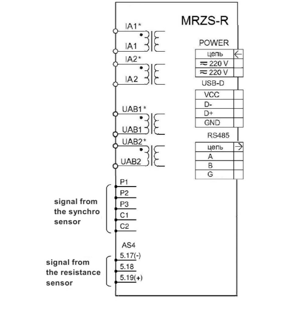
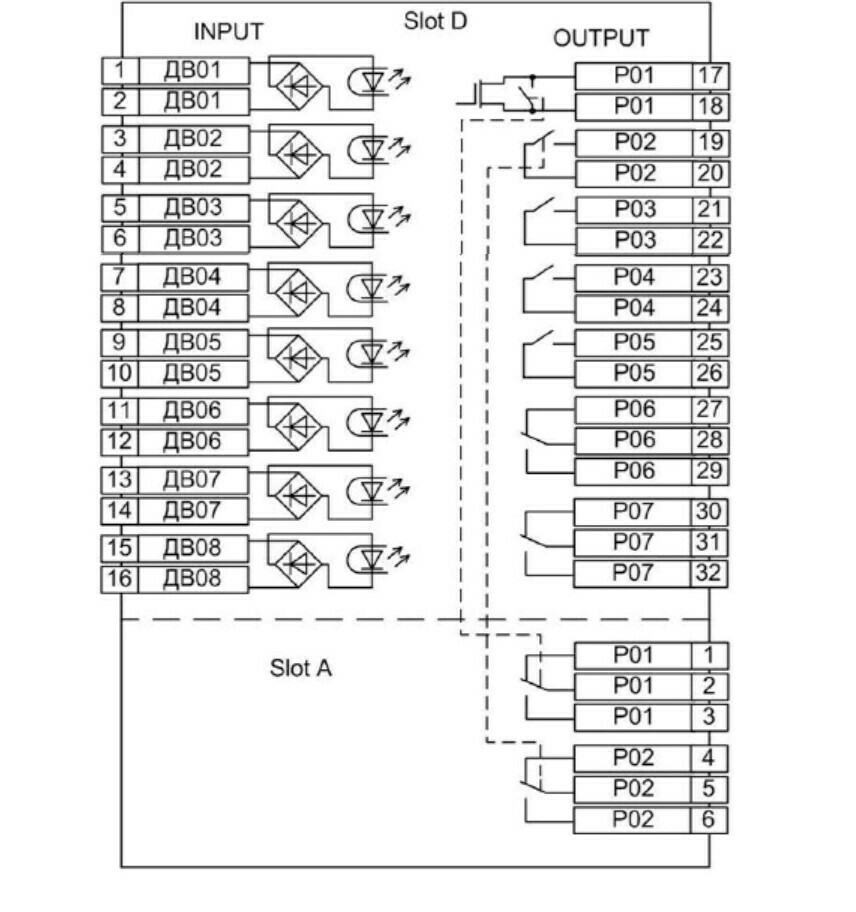
сonnection diagram-MRZS-R-back view
Software WisiNet_2 for МРЗС-05Л, МРЗС-05Д, MRZS
Please pay attention! Many new versions of devices have been added for corrective work, the program must save the /data folder (with your archives), delete the WisiNet2 installation program, download the archive from the website and install the Wisinet2 program and replace the new /data folder with your previous oneDownload Wisinet 2
If you have a version of the WisiNet_2 program higher than v.22.1, you can simply update the jar fileUpdate programm Wisinet 2 download


