
MРЗС-05Д-04

The MРЗС-05Д-04 device is designed to protect three-phase asynchronous electric motors with a power of 1 to 710 kW, operating in a 0.4 kV network with an isolated, compensated or grounded neutral with a frequency of 50 Hz. The controlled input voltage is also the supply voltage of the device. Offset of protection against inrush currents of the electric motor (starting time, setting range - from 1 to 200 s) is provided.
Provides control and measurement of the following quantities:
- phase currents:
- a) when using internal current sensors - from 0.15 to 450 A, the range of setting the rated current of the electric motor Inom - from 1 to 30 A;
- b) when using external current transformers - from 0.15 to 75 A, the transformation ratio of external current transformers - from 10 to 300, the range of setting the rated current of the electric motor Inom - from 10 to 1500 A;
- zero sequence current from 0.005 to 2.4 A, transformation ratio of external current transformer - from 1 to 1000;
- line voltages from 25 to 500 V;
- power supply frequency from 48.5 to 51.5 Hz;
- insulation resistance before starting the electric motor from 0.05 to 2.2 MΩ;
- heating temperature of the electric motor from 0 to + 110 ° C (up to 4 external temperature sensors);
- the total operating time of the electric motor (motor resource) up to 999999 hours.
Relay protection functions:
- three-stage overcurrent protection , has the following stages:
- 1 - stage with definite time delay (current cutoff), the multiplicity of setting the operating current - from 6 to 12 In, the response time - from 50 to 75 ms;
- 2 - stage with definite time delay (rotor blocking), frequency of setting the operating current - from 2 to 6 Inom, operating time - from 0.1 to 10.0 s;
- 3 - stage with current-dependent time delay (normal-inverse characteristic in accordance with IEC 255-4 and characteristic of the RT-80 relay type, meet the requirements of IEC 60255-151);
- minimum overcurrent protection (no-load), the frequency of setting the operating current - from 0.2 to 0.75 In, the response time - from 1 to 600 s;
- current asymmetry (phase imbalance) protection, operation setting range - from 10 to 55%, response time - from 1 to 120 s;
- protection for minimum line voltage, operating voltage setting range - from 285 to 342 V, response time - from 1 to 600 s in the presence of phase ones and 1 s in their absence;
- protection for maximum line voltage, operating voltage setting range - from 418 to 475 V, response time - from 1 to 600 s in the presence of phase ones and 1 s in their absence;
- protection against incorrect phase sequence before starting;
- protection against breakage (voltage and current) and sticking (voltage) phases, response time - 1 s;
- earth fault protection (by zero sequence current 3I0), operating current setting range - from 0.015 to 2.0 A, operating time - from 0.1 to 100 s;
- protection to reduce the insulation resistance (only in a network with a solidly grounded neutral, control before starting), the response resistance setting range is from 0.3 to 1.5 MΩ, the response time is 1 s;
- protection against overheating (using external temperature sensors, up to 4 pcs.), the range of setting the response temperature separately for each sensor - from 45 to 99 ° C, return - from 35 to 80 ° C, response time - no more than 4 s;
- protection against sticking (welding) of the contacts of the magnetic starter (or contactor).
Automation functions:
- automatic switching on of the standby electric motor (ATS);
- switching the star / delta motor wiring diagram;
- start / stop the motor using the buttons on the keyboard of the device.
Discrete inputs:
- the device has one digital input to control the operation logic;
- a discrete input operates on DC or AC voltage;
- current consumption through the discrete input circuit - no more than 5 mA.
Discrete outputs:
- number of digital outputs:
- a) one control (OUTPUT 1), with one changeover contact, is designed to control a magnetic starter (or contactor) that turns on / off the electric motor;
- b) one functional (OUTPUT 2), with one changeover contact, assigned in accordance with the device operation algorithm;
- switching capacity of digital output relay contacts - 16 A, ~ 250 V at cos φ = 1.
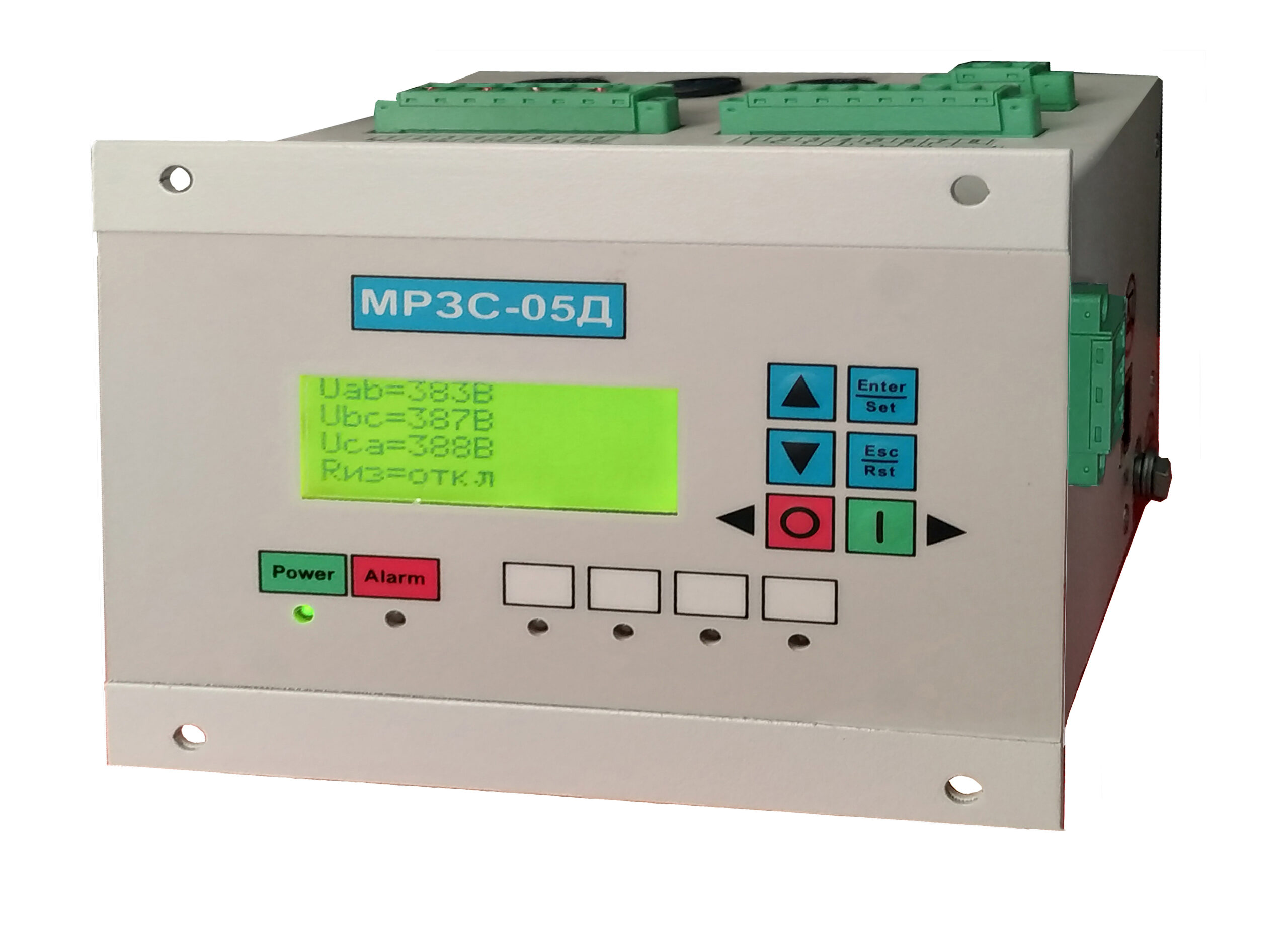
Display and keyboard:
- the device has one mini-display based on a four-line LCD for displaying information about the value of the measured values, date and time counted by the real-time clock, performing the necessary configuration of the device in the mode of manual programming of the parameters of protection and automation functions, as well as displaying the reason for the protection operation;
- to display the state of the monitored network and triggering of protection and automation, the device has six LED indicators: "Power", "Alarm" and four freely assignable "HL1" - "HL4" for any protection function;
- the keyboard has six buttons for manual control of the device.
Alarm log:
- the log records the values of the measured input signals by the device at the moment of triggering the protection organ with reference to the date and time counted by the real time clock, as well as the type of the accident that occurred;
- the maximum number of recorded alarms is 15.
Interfaces and communication protocols:
- one RS 485 port, exchange protocol - Modbus RTU.
Temperature sensors:
- up to 4 temperature sensors TD-04 can be connected to the device;
- one temperature sensor is connected to the device directly, two or more through the BRT-04 expansion unit;
- maximum cable length from the device to the temperature sensor (taking into account the length to the expansion unit) - 50 m.
Construction:
- the device has a tunnel-type design that allows the monitored current circuits of phases A, B and C to be connected to internal sensors or external current transformers without mechanical fastening;
- execution options:
- a) with top connectors;
- b) with bottom connectors;
- there is a DIN-rail mount on the back of the device;
- for attaching the device to the control cabinet door, there are four holes in the front panel;
- temperature sensors TD-04 are attached to the motor casing using screws with a washer;
- BRT-04 expansion unit has fasteners for mounting on a DIN rail.
Overall and connecting dimensions MRZS-05D-04
Overall dimensions МРЗС-05Д-04 стр1
Overall dimensions МРЗС-05Д-04 стр2
Overall dimensions МРЗС-05Д-04 стр3
Overall dimensions МРЗС-05Д-04 стр4
Overall dimensions БРТ
Connection scheme MRZS-05D-04
scheme with external vehicles ТС
scheme with internal ТС
star-delta scheme
diagram from БРТ-04
Software WisiNet_2 for МРЗС-05Л, МРЗС-05Д, MRZS
Please pay attention! Many new versions of devices have been added for corrective work, the program must save the /data folder (with your archives), delete the WisiNet2 installation program, download the archive from the website and install the Wisinet2 program and replace the new /data folder with your previous oneDownload Wisinet 2
If you have a version of the WisiNet_2 program higher than v.22.1, you can simply update the jar fileUpdate programm Wisinet 2 download