
Categories
MРЗС-05Л AИAР.466452.001-33
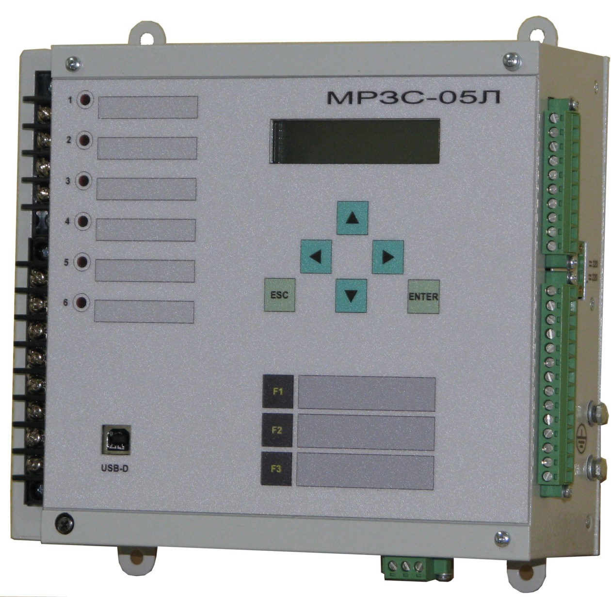

Used as protection of the feeder cable and overhead lines. The directional earth-fault protection allows to install the device on the connections, the capacitive current of which is 40% or more of the capacitive current of the substation.
Performs the following functions:
Provides control and measurement of the following values:
- phase currents at a frequency of 50 Hz with a nominal value Iн = 5 A in the range from 0.1 to 30 Iн;
- zero-phase-sequence current from 0.01 to 2 A.
- residual voltage with a nominal value of 100 V.
Relay protection functions:
- three-stage overcurrent protection (OСP), can be of two versions, optionally:
- 1) three-stage OCP with current indefinite time delay;
- 2) three-stage OCP, where the first and third stages with a current indefinite time delay and the second - with a current definite time delay, hasa characteristic of the relay RT-80.The operating time of the second-stage OCP type RT-80 is determined by the formula: t-time of operation; I - input current; Iset - current setting of the second-stage of the OCP; Tset - is the set-point for the time of operation of the second stage of the OCP.
- Return rate of the fault detector not more than 0,95.
- directional ground fault protection GFP: the angle between the current 3Io and the voltage 3Uo (the current is behind the voltage) corresponding to the middle operating zone equals to 90 degrees; protection zone for the protection of the angle from 0 ± 10 degrees to 180 ± 10 degrees; operates on the forward or reverse direction of power;
- non-directional ground -fault protection by 3Io, (analogue of relay PTZ-51);
- zero-phase-sequence voltage protection 3Io (RNN) operates with or without time delay;
- circuit-breaker failure protection (CBFP) with current control: circuit-breaker failure protection is initiated at OСP response to cut-off or via discrete input. The circuit-breaker failure protection has two stages in response time
Automation functions:
- switch control. The circuit breaker can be switched on and off both from the device and via a discrete input (pulsed). If there is a command to cut off the circuit breaker, the on signal is blocked;
- acceleration of protection. Automatic acceleration of the second stage overcurrent protection is entered at the command of the circuit breaker closing;
- single-stage autoreclosing (AR). The AR is started from OCP. If a blocking signal is present at the discrete input, the blockage of the AR is carried out, if it disappears, the AR blockage is removed;
- UFLS (FAR). When the "UFLS/FAR" signal appears on the discrete input, the circuit breaker is switched off. When the signal disappears at the input, the AR starts.
Defined functions:
- number of defined functions - 5;
- the source commands of the functions being defined can be other defined functions, discrete inputs, discrete outputs, and protection operation.
- Operation of the device is provided for both direct and alternating current, as well as backup power from short-circuit currents (analogue of AC unit).
Event logger of disturbance recorder oscillograms
- parameterizable recording time:
- pre-emergency process - from 0,1 to 5 s.
- emergency process - 1 to 20 s.
- total length of records - 150 s.
Discrete event recorder:
- 100 recent events;
- up to 50 entries in each accident with a discreteness in time - 1 ms;
- for each accident the following are recorded:
- all discrete signals during the time of presence of the trigger signal of the recorder;
- the maximum value of the phase current with the fixation of the currents of the three phases, 3Io and the voltage of 3Uo at the moment of fixing the maximum current, while the operation of the protection against phase currents;
- the maximum value of the current 3Io with the fixation of the currents of the three phases and the voltage of 3Uo at the moment of fixing the maximum current, when the current protection is 3Io;
- the maximum value of the voltage is 3Uo with the fixation of the currents of the three phases and 3Io at the moment of fixing the maximum voltage when the voltage protection is 3Uo.
Number of freely programmable inputs, outputs, indicators:
- discrete inputs - 5;
- discrete relay outputs - 6;
- LED indicators - 6.
Overall and mounting dimensions of MRZS-05L AIAR.466452.001-13


")
")
")
Connection diagram MRZS-05L AIAR.466452.001-13, (-33)
 str1")
 str2")
Software WisiNet_2 for МРЗС-05Л, МРЗС-05Д, MRZS
Please pay attention! Many new versions of devices have been added for corrective work, the program must save the /data folder (with your archives), delete the WisiNet2 installation program, download the archive from the website and install the Wisinet2 program and replace the new /data folder with your previous oneDownload Wisinet 2
If you have a version of the WisiNet_2 program higher than v.22.1, you can simply update the jar fileUpdate programm Wisinet 2 download